
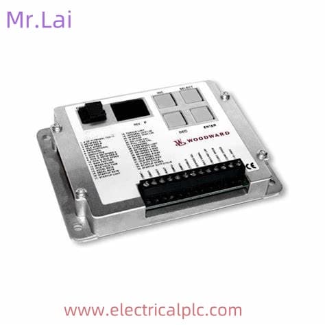
8406-121 Woodward Ship Spare Parts
The 8406-121 is a microprocessor-based digital governor controller produced by Woodward, belonging to its classic 505 series.
It is primarily designed for speed control and protection of steam turbines. Below is a detailed introduction to this product:
I. Product Overview
- Brand and Model: Woodward 8406-121
- Series: 505 Series Digital Governor
- Type: Microprocessor-based controller
- Purpose: Specifically designed for steam turbines to control their speed and provide overspeed protection.

II. Core Functions
- Speed Control:
- 8406-121 Precisely controls the speed of steam turbines by adjusting steam inlet flow.
- Supports single-range or split-range actuators to accommodate turbines of different sizes.
- Overspeed Protection:
- Incorporates triple independent overspeed protection logic to ensure rapid shutdown in case of overspeed, preventing equipment damage.
- Provides an overspeed test button for convenient on-site testing of protection functions.
- Emergency Shutdown:
- Equipped with an emergency stop button for immediate shutdown in emergency situations.
- System Protection:
-
- Automatically switches control modes upon sensor failure to ensure uninterrupted system operation.
- Offers local/remote control priority selection to adapt to different operational scenarios.
-
1. Introduction
The AC speed control system usually uses IGBT pulse width modulation drivers to control the execution motor to operate in four quadrants, thereby meeting the
high-precision and high real-time requirements of the control system. The driver is the core part of the AC speed regulation unit in the control system, and its quality and performance
directly affect the accuracy and performance of the entire control system. However, once the driver malfunctions during use, it will affect the normal operation of the
entire control system. Therefore, it is necessary to design and develop a comprehensive performance testing system for the driver to quickly troubleshoot and ensure the performance quality of the control system.
2. Working principle of the driver and technical characteristics of the testing system
Figure 1: Schematic diagram of the drive speed regulation system
Drive speed regulation can generally be divided into four parts: rectification, DC holding, inversion, and control. The current regulator compares and adjusts the actual current
value with the given value, while the speed regulator obtains the actual speed value through the speed measurement motor and rotor position detection, and adjusts the speed value.
Drivers belong to high-power precision devices, which may cause mutual interference with the outside world, affecting normal operation. The noise signals generated by other
devices on the same power supply may also enter the driver through radiation and power conduction, and the high-order harmonics and radio wave noise generated by the driver
can easily affect the power grid and surrounding equipment. Eliminating interference and ensuring the normal
operation of the equipment is a major feature and challenge of this system. The standard grounding method is adopted in the design, and filtering devices are connected at the
front and rear ends of the driver. Surge current limiting circuits are connected in series in the circuit to effectively avoid mutual interference and ensure accurate and reliable testing signals.
III. Technical Specifications
- Power Supply: 18-32 VDC, supporting 24VDC input.
- Display: Two-line x 24-character LED display for clear indication of operating status and parameters.
- Enclosure: NEMA 4X or IEC 60529 IP56 rated for protection against harsh industrial environments.
- Inputs/Outputs:
- Inputs: 6 programmable current inputs, 16 discrete contact inputs.
- Outputs: 2 actuator outputs, 8 relay outputs, 6 programmable current outputs.
- Communication Interfaces: 8406-121 Supports RS-232, RS-422, and RS-485 hardware interfaces for easy integration with host computers or other devices.
- Software: Equipped with OpView™ and 505View software for parameter configuration, monitoring, and fault diagnosis.
- Operating Temperature: -20 to +60°C (some models support -4 to +140°F).
- Storage Temperature: -40 to +85°C (some models support -40 to +185°F).
- 8406-121 Weight: Approximately 9.11 pounds (4.13 kilograms).
IV. Application Scenarios
- Steam Turbine Control: 8406-121Suitable for steam turbines of various sizes, including industrial steam turbines, small grid turbo-generators, and turboexpanders.
- Single Extraction and Admission Applications: Designed for operating steam turbines in single extraction and/or admission applications.
- On-Site Programming: Allows on-site operators to program and adjust parameters through an integrated operator control panel, adapting to different operating conditions.
V. Product Advantages
- High Reliability:
- Microprocessor-based design ensures precise control and stability.
- Triple independent overspeed protection logic provides multiple layers of safety.
- Flexibility:
- Supports various actuator and sensor configurations to accommodate different turbine models.
- Offers a rich set of input/output interfaces for easy system expansion and integration.
- Ease of Use:
- Two-line x 24-character LED display provides an intuitive operating interface.
- A 30-key multifunctional keyboard simplifies parameter configuration and operation.
- Compatibility:
- Supports multiple communication protocols for easy integration with DCS, PLC, and other systems.
- Provides OpView™ and 505View software for remote monitoring and fault diagnosis.

Woodward ship parts module debugger controller actuator generator set
5461-654 Woodward Ship Spare Parts,
8237-2597 Woodward ProTech 203,
5464-554 WOODWARD Debugger unit,
9904-254 Woodward Ship Spare Parts,
5464-697 Woodward overspeed protector,
5421-112 Woodward ProTech 203,
5464-661 WOODWARD Debugger unit,
5439-751 Woodward overspeed protector,
5439-730 WOODWARD Debugger unit,
5464-727 Woodward turbine controller,


Reviews
There are no reviews yet.