
5437-076 WOODWARD Debugger unit
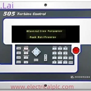
The 5437-076 is a microprocessor-based digital governor controller produced by Woodward, belonging to its classic 505 series.
It is primarily designed for speed control and protection of steam turbines. Below is a detailed introduction to this product:
I. Product Overview
- Brand and Model: Woodward 5437-076
- Series: 505 Series Digital Governor
- Type: Microprocessor-based controller
- Purpose: Specifically designed for steam turbines to control their speed and provide overspeed protection.
II. Core Functions
- Speed Control:
- 5437-076 Precisely controls the speed of steam turbines by adjusting steam inlet flow.
- Supports single-range or split-range actuators to accommodate turbines of different sizes.
- Overspeed Protection:
- Incorporates triple independent overspeed protection logic to ensure rapid shutdown in case of overspeed, preventing equipment damage.
- Provides an overspeed test button for convenient on-site testing of protection functions.
- Emergency Shutdown:
- Equipped with an emergency stop button for immediate shutdown in emergency situations.
- System Protection:
-
- Automatically switches control modes upon sensor failure to ensure uninterrupted system operation.
- Offers local/remote control priority selection to adapt to different operational scenarios.
-
How to wire the BLDC driver
The wiring method of BLDC (brushless DC motor) drivers may vary depending on the specific driver model and usage scenario, but generally speaking,
the wiring of BLDC drivers includes the following key parts:
1. Power wiring: BLDC drivers require external power supply. Usually, power wiring includes connecting the positive and negative poles of a DC
power source (such as a battery) to the power input terminal of the driver.
2. Motor wiring: The BLDC driver names the three phase lines on the drive motor shaft as phase A, phase B, and phase C. Motor wiring generally includes
connecting the A-phase, B-phase, and C-phase wires of the driver to the corresponding phase wires of the motor.
3. Sensor wiring (if any): Some BLDC drivers require the connection of sensors such as Hall sensors or encoders to obtain information on the motor”s
rotational position and speed. Sensor wiring generally includes connecting the output signal line (usually three wires) of the sensor to the corresponding input terminal of the driver.
4. Control signal wiring: BLDC drivers typically require receiving control signals to control parameters such as motor speed and direction. The control signal wiring
usually includes connecting the speed control, direction control, and enable pins of the driver to the corresponding output pins of the controller (such as microcontroller or PLC).
It should be noted that the wiring method of BLDC drivers is related to the specific driver model, and should refer to the selected driver”s manual or technical manual for
correct wiring. In addition, it is recommended to ensure that the polarity and wiring of the power and signal lines are correct before wiring, and to follow the rated current and voltage requirements of the motor and driver to ensure safe and normal operation.
III. Technical Specifications
- Power Supply: 18-32 VDC, supporting 24VDC input.
- Display: Two-line x 24-character LED display for clear indication of operating status and parameters.
- Enclosure: NEMA 4X or IEC 60529 IP56 rated for protection against harsh industrial environments.
- Inputs/Outputs:
- Inputs: 6 programmable current inputs, 16 discrete contact inputs.
- Outputs: 2 actuator outputs, 8 relay outputs, 6 programmable current outputs.
- Communication Interfaces: 5437-076 Supports RS-232, RS-422, and RS-485 hardware interfaces for easy integration with host computers or other devices.
- Software: Equipped with OpView™ and 505View software for parameter configuration, monitoring, and fault diagnosis.
- Operating Temperature: -20 to +60°C (some models support -4 to +140°F).
- Storage Temperature: -40 to +85°C (some models support -40 to +185°F).
- 5437-076 Weight: Approximately 9.11 pounds (4.13 kilograms).
IV. Application Scenarios
- Steam Turbine Control: 5437-076Suitable for steam turbines of various sizes, including industrial steam turbines, small grid turbo-generators, and turboexpanders.
- Single Extraction and Admission Applications: Designed for operating steam turbines in single extraction and/or admission applications.
- On-Site Programming: Allows on-site operators to program and adjust parameters through an integrated operator control panel, adapting to different operating conditions.
V. Product Advantages
- High Reliability:
- Microprocessor-based design ensures precise control and stability.
- Triple independent overspeed protection logic provides multiple layers of safety.
- Flexibility:
- Supports various actuator and sensor configurations to accommodate different turbine models.
- Offers a rich set of input/output interfaces for easy system expansion and integration.
- Ease of Use:
- Two-line x 24-character LED display provides an intuitive operating interface.
- A 30-key multifunctional keyboard simplifies parameter configuration and operation.
- Compatibility:
- Supports multiple communication protocols for easy integration with DCS, PLC, and other systems.
- Provides OpView™ and 505View software for remote monitoring and fault diagnosis.
Woodward ship parts module debugger controller actuator generator set
5463-716 Woodward Ship Spare Parts,
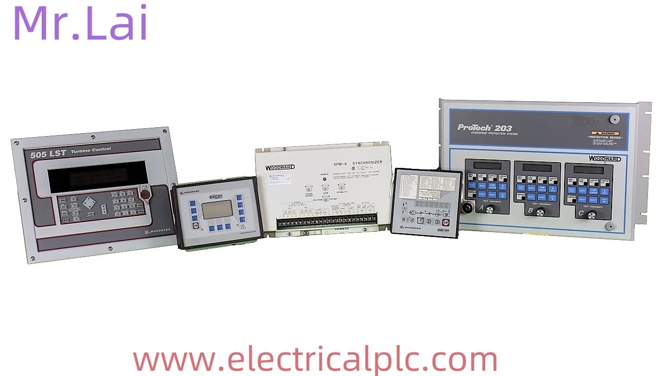
9907-1177 Woodward ProTech 203,
5437-686 Woodward turbine controller,
5463-779 Woodward turbine controller,
5464-828 Woodward turbine controller,
5501-432 Woodward overspeed protector,
8238-002 Woodward speed control module,
8236-043 Woodward ProTech 203,
9905-462 WOODWARD Debugger unit,
5461-654 Woodward Ship Spare Parts,
Reviews
There are no reviews yet.